Network management
Configuring the network infrastructure for EBM servers is a crucial step in ensuring the reliability, security, and performance of your information systems.
In this article, we will cover the key aspects of configuration, including the use of public and private networks, uplink configuration, the application of disaggregation to optimize traffic, and the use of additional IPs (also known as alias IP) for flexible network address management. These elements will help you create an efficient and scalable network infrastructure to meet your business needs.
Understanding public and private networks
Each server is equipped with at least two NICs (Network Interface Cards). One port on each NIC is used for a private network connection, and the other is for a public network connection.
Combining public and private networks offers several advantages:
- Flexibility and scalability: using both types of networks allows for balancing between accessibility and security, which is especially important for hybrid and cloud solutions
- Enhanced security: data that should not be accessible from the internet can be transmitted through private networks, reducing the risk of information leakage
- Load separation: public networks can handle user requests, while private networks manage internal operations, improving overall system performance and reliability
Thus, public and private networks play key roles in the architecture of EBM servers, ensuring the availability and security of data and services.
Public networks
Public networks are used for interaction between servers and external devices or users via the Internet. They are typically used for hosting websites, web applications, APIs, email servers, and other services accessible to users over the Internet.
Key concepts of public networks include:
- IP addresses: public IP addresses are unique and reachable externally
- Security: public networks employ security measures such as firewalls, VPNs, and other technologies to protect against unauthorized access and cyber threats
- Internet accessibility: servers connected to public networks are accessible from anywhere via the internet
Private networks
Private networks are used for internal communication between servers and devices, ensuring secure data transfer for tasks like server-to-server communication, databases, backups, etc., bypassing the public internet.
Key concepts of private networks include:
- IP addresses: devices use private IP addresses that are not routed through the Internet and are not accessible from the outside
- Security: private networks provide a high level of security as access is restricted by internal rules and security policies
- Direct connect: private networks enable direct connect, providing a direct, fast, and reliable connection
- L2 segmentation: private networks enable L2 segmentation to isolate traffic and improve management through the use of virtual local area networks (VLANs)
Network size
The available network sizes depend on the type of location and the network architecture at that location. The network size determines the number of available IP addresses in a subnet. Subnets are used to divide larger networks into smaller segments, allowing for easier management of network resources and increased security. CIDR notation (Classless Inter-Domain Routing) is used to designate blocks of IP addresses and subnet masks, formatted as: IP address / number of bits in the subnet mask.
For example, a /29 prefix indicates that out of the 32 bits of the subnet, 29 bits are used for the network part of the address, leaving 3 bits for hosts. This means the subnet can contain 8 IP addresses:
- 5 can be assigned to user devices and our infrastructure devices
- 1 is reserved for the network address
- 1 is reserved for the gateway on the switch
- 1 is reserved for the broadcast address
Suppose the network IP address is 213.3.172.48, and the network size is /29. In this case, the IP addresses will be allocated as follows:
213.3.172.48– reserved for the network213.3.172.49– address of the first (r1) switch in the switch group (rbridge1)213.3.172.50– address of the second (r2) switch in the switch group (rbridge2)213.3.172.51– address of the virtual switch of the switch group. This address is the gateway address in the network213.3.172.52– interface IP address (the first available IP address assigned to the server interface)213.3.172.53,213.3.172.54– available unused IPs213.3.172.55– reserved broadcast address of the network
Addresses of private and additional networks are allocated in the same manner.
To ensure redundancy, each EBM server is allocated two /29 networks: a private and a public network. This provides 3 usable IP addresses, of which we provide only one as a service.
We cannot add PTR records to the remaining two IP addresses. For this, you can order an additional IP or an additional network and then assign PTR to it.
Network configuration
In the Customer Portal, you can view networks and network pools allocated to your account and manage networks assigned to individual Enterprise Bare Metal servers.
To view the list of networks, go to IP Management and open the Networks or Network Pools tab.
The Networks tab displays only networks created from allocated network pools and networks attached to Enterprise Bare Metal servers. Other networks are not shown.
To view and manage networks assigned to a specific server:
- Navigate to Enterprise Bare Metal
- Select the server you need to configure the networks for and click the Network tab
The Default network is configured automatically during OS installation, whereas Additional networks require manual configuration.
How to add a network
To add a network:
- Navigate to Enterprise Bare Metal and select the server to which you want to add a network
- Click the Network tab and click Add Network
- In the Network type dropdown, select the desired network type and size (e.g.,
Public IPwith a/27prefix) Available options include:- Public IP
- Private IP
- Public IPv6 (can be assigned to a server only once; not available in locations with reduced redundancy)
Note: available network types and subnet sizes depend on the server's operating system and the location type (standard or reduced redundancy). For more details, see the Network size and Billing and limitations for additional IPs and networks sections.
- Click Add
The new network will be provisioned within approximately 5 minutes. Provisioning time depending on the number of allocated networks.
How to remove a network
To remove a network:
- Navigate to Enterprise Bare Metal and select the server to which you want to remove a network
- Click the Network tab and click the trash can icon next to the network you want to delete
- Confirm the action by clicking Proceed
If the EBM server has more than one IP address for either the private or public network, you cannot remove the default IP address, only the additional ones.
How to order additional IP address(es)
Additional IP addresses can be assigned to one or more network interfaces of an EBM server. These IPs can be added to an L2 segment.
Key aspects
- Efficient use of a single interface: additional IPs enable one interface to handle traffic for multiple IP addresses, saving resources and simplifying network management
- Increased network flexibility: administrators can organize various services and applications on a single server using different IP addresses. This also allows hosting multiple websites on one server, each with its own IP address
- Enhanced security and service isolation: different services (e.g., web server and mail server) can be assigned separate IP addresses, improving security and allowing specific access controls for each application or service
- Simplified traffic management: managing traffic related to different IP addresses is simplified, allowing for more detailed control and routing of network traffic
Additional IP management requires a deployed L2 segment of the public type network. For more details, refer to the L2 Segments - Getting started article.
To order additional IP, complete the following steps:
- Navigate to Enterprise Bare Metal and select the server to which you want to add an additional IP
- Click the Network tab and click Add Network
- Select Public IP
- Choose the
/32network size
Note:
/32represents a single IP address, not a range. It's used to assign an individual additional IP to an existing network interface without allocating a subnet, gateway, or broadcast address.
- In the Quantity field, select the number of IP addresses to add.
Note: the Customer Portal has a limit of creating no more than 64 additional IP addresses. For more details, see the Billing and limitations for additional IPs and networks section.
- Click Add
The additional IP address(es) will be allocated within approximately 5 minutes.
How to manage uplinks
To manage uplinks:
- Navigate to Enterprise Bare Metal → Manage
- Choose the server and click Details
- Scroll to the Uplinks section and click Change
In the opened window, you can manage the following configurations:
Public uplink port
- 1 Gbps with redundancy: this is a public connection with a bandwidth of 1 gigabit per second
- The "with redundancy" option means that there are two or more physical connections providing network or internet access. If one connection fails, traffic automatically switches to the backup connection, enhancing network reliability and fault tolerance
Private uplink port
- 1 Gbps without redundancy: this is a private connection with a bandwidth of 1 gigabit per second
- The "without redundancy" option means that there is only one physical connection. If this connection fails, network or internet access will be lost until the issue is resolved. This option is provided for free
Public bandwidth plan
- The public bandwidth plan determines the amount of data that can be transmitted through the public connection.
- For example, a plan with "By traffic amount 20002 GB" means the server can send and receive up to 20002 gigabytes of data during the billing period, which is one month. Exceeding this limit will incur additional charges at the rate of €0.03 per additional gigabyte
Uplinks cannot be changed in the Customer Portal more than once per day.
How to disaggregate an uplink port
Disaggregating an uplink port means separating or altering the routing of traffic managed by that port. This process may be necessary to redistribute traffic load and enhance overall network performance.
To disaggregate an uplink port:
- On the uplink configuration page, next to the required port, click Disaggregate
- In an opened window, confirm your action by clicking Disaggregate
- To confirm this action, enter your account password in the pop-up window and click Continue
Note: disaggregating will disable redundancy for the port if it was previously enabled.
Independent uplink mode
For redundant uplinks, the Uplinks card in the Customer Portal can also show a third mode, Independent, alongside Aggregated and Disaggregated. Independent mode keeps both network interface cards of an uplink active at the same time, without combining them into a single logical connection. This mode is read-only in the Customer Portal: enabling or disabling it is done by Servers.com support.
Reinstalling the server's operating system or booting it into rescue mode switches an uplink out of Independent mode automatically: the uplink returns to Aggregated mode, except when the target operating system is VMware ESXi, in which case it switches to Disaggregated mode instead. The Customer Portal shows a confirmation warning before either action if any uplink is currently in Independent mode.
Tagged trunks in an L2 segment
Introduction
Note: VLAN, VXLAN, and VLAN tagging are complex concepts. This article is not intended as an introduction to those concepts.
The L2 segments service (also known as broadcast domains) allows the creation of virtualized Layer 2 (L2) subnets or segments over an underlying Layer 3 (L3) network. From the technical standpoint, an L2 segment is a set of VLANs interconnected using the VXLAN protocol. VLANs are provisioned per L2 segment, per server rack.
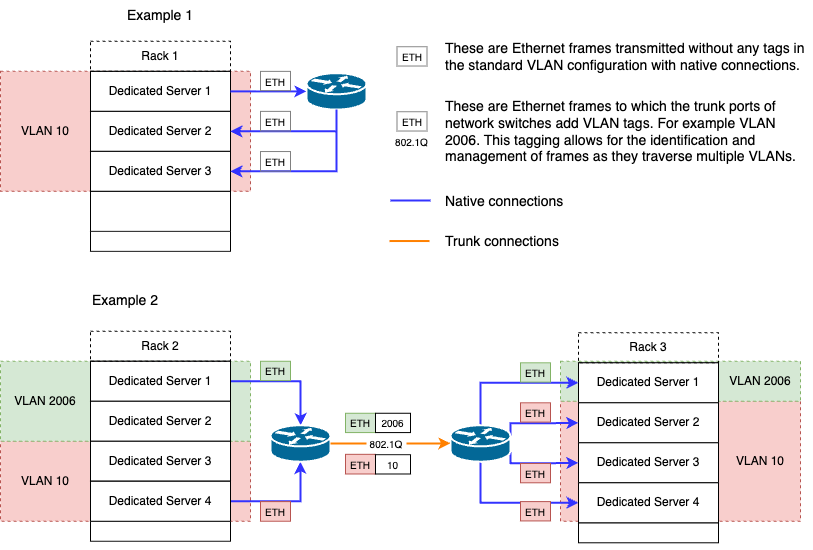
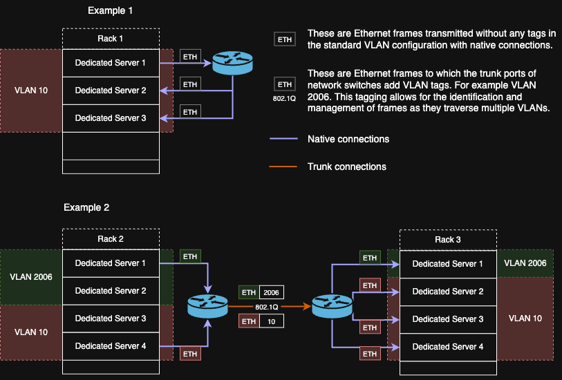
These are Ethernet frames transmitted without any tags in the standard VLAN configuration with native connections.
These are Ethernet frames to which the trunk ports of network switches add VLAN tags. For example VLAN 2006. This tagging allows for the identification and management of frames as they traverse multiple VLANs.
How to configure tagged trunks
When adding a server to an L2 segment with a trunk type connection, proper network operation requires configuring IEEE 802.1Q tagging in the server's operating system. For this, you will need the VLAN ID number.
Getting VLAN ID for the server
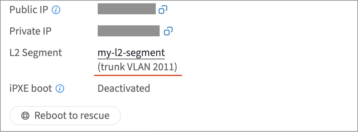
You can find it in two places in the Customer Portal:
-
Enterprise Bare Metal -> your server -> Details section ->
-
L2 Segments -> your L2 segement -> In the Members row, click the number to open the network members window and view the VLAN ID
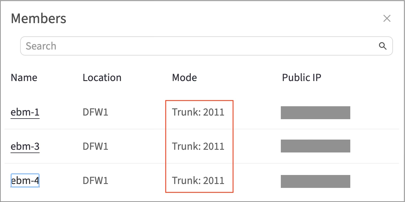
Note: VLAN IDs for different servers within the same L2 segment may vary from rack to rack. Therefore, you should obtain the VLAN ID for each server individually.
Using the ip utility
The ip utility comes with most Linux distributions. To enable 802.1Q tagging on the aggi interface with a static IP address (for example, 172.16.0.1/16) and VLAN ID (for example, VLAN ID 2006), execute the following command:
ip link add link aggi name vlan2006 type vlan id 2006
ip address add 172.16.0.1/16 dev vlan2006
ip link set vlan2006 up
Note: this configuration will not persist after a reboot.
Using interface configuration files
To create a subinterface with 802.1Q tagging enabled, VLAN ID (e.g., VLAN ID 2006), and a static IP address (e.g., 172.16.0.1/16) on the Ethernet interface aggi, follow the instructions provided below.
- Add a new configuration file: `/etc/sysconfig/network-scripts/ifcfg-aggi.2006`

  Ensure that the file name follows the naming convention for VLAN interfaces described in the naming scheme for VLAN interfaces.

- Edit the file and add the following configuration:
ONBOOT=yes TYPE=Ethernet VLAN=yes DEVICE=aggi.2006 BOOTPROTO=static IPADDR=172.16.0.1 NETMASK=255.240.0.0
- Restart the network service:
systemctl restart network
- Install the VLAN package:
apt update && apt install vlan
- Add configuration to the `/etc/network/interfaces` file:
auto aggi.2006 iface aggi.2006 inet static address 172.16.0.1 netmask 255.240.0.0 vlan_raw_device aggi
Configuring tagged trunks on Windows Server 2012 R2 / 2016 / 2019
When a tagged VLAN is configured on the switches, to configure tagged trunks, you need to specify this VLAN on the server. To do this, complete the following steps:
- Go to NIC teaming settings and navigate to the Teams section
- Select the team group (in this case,
aggi) for which you need to create a VLAN interface - In the Adapters and Interfaces section, click the drop-down list Tasks and select Add Interface
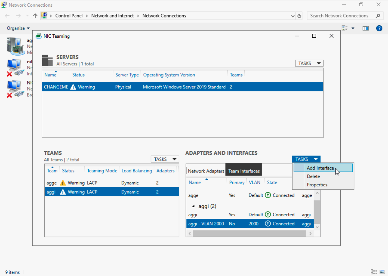
- Save the settings by clicking Apply, and then click OK
The VLAN interface will be created, and you can now configure the necessary network on it.
Billing and limitations for additional IPs and networks
| Billing | Proration | Limitations | Notes | |
|---|---|---|---|---|
| Additional IPv4 networks | Pre-paid | Prorated by days | No more than 2 public networks: one main public network + one additional network. No more than 2 private networks: one main private network + one additional network. No more than 72 public IP addresses. No more than 72 private addresses in networks | All IP addresses in the network are billed, not just the usable ones |
| Additional IPv6 networks | Pre-paid | Monthly cost, regardless of the number of days used | Only one /64 IPv6 network | The network cost is fixed and does not depend on the number of addresses |
| Additional IP | Pre-paid | Prorated by days | No more than 64 additional IPs | |
| Uplink (with redundancy) | Pre-paid | Prorated by days | Only one public port and one private port |
Traffic billing
Traffic within the private network is free of charge, including traffic between servers located in different data centers. Incoming traffic is also free and unlimited.
Only outgoing traffic on the public network is billed, regardless of whether the primary, additional public network, or additional IP was used. Traffic overuse is calculated based on the rate.
To monitor traffic expenses, keep an eye on the traffic usage statistics on the server page in the Customer Portal under the Traffic usage section.
Do not ignore notifications about traffic consumption. The Customer Portal sends automatic notifications to the primary and technical contacts when 50%, 80%, and 100% of the traffic package has been consumed.