
Network infrastructure
Network infrastructure
The servers.com data center network infrastructure is based on three physically isolated networks:
- Public network (Internet) – for external traffic
- Private network (Global Private Network, GPN) – for secure, isolated communication between servers
- Out-of-band (OOB) management network – for access and remote server management (e.g. iDRAC)
The public and private networks are based on a resilient Layer 3 fabric using a two-tier leaf-spine topology.
Leaf-spine topology
The leaf-spine is a modern network architecture that includes two layers of switches:
- Leaf switches (also known as Top-of-Rack, or ToR switches)
- Spine switches (aggregation/core layer)
Each leaf switch connects to at least two spine switches, creating a highly resilient full-mesh architecture. This architecture minimizes latency and guarantees that traffic between any two servers can traverse the network in no more than three hops.
Leaf-spine topology scheme:
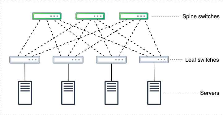
Leaf switches
Leaf switches are installed in server racks and provide direct connections to the servers. Each server is connected to two independent leaf switches - one link per switch. The leaf switches aggregate traffic from servers and forward it to the spine layer.
Spine switches
Spine switches form the network backbone, interconnecting all leaf switches. These switches do not connect directly to servers. Instead, they forward traffic between leaf switches and up to the core routing layer, maintaining balanced traffic distribution and low latency.
Redundancy
At servers.com, every network layer - leaf, spine, and core – is fully redundant in both the private and public networks.
The core layer is composed of routers that connect the infrastructure to external carriers and other servers.com data center locations. Each public network core router connects to multiple Tier 1 providers. Private network routers maintain at least two independent connections to the rest of the infrastructure.
This hardware-level redundancy protects against component failures, including:
- Carrier outages
- Hardware failures at any network layer
- Network interface failure on a server
L3 fabric
In addition to physical redundancy built into the hardware layer, the L3 fabric architecture provides protocol-level protection and efficient routing behavior to ensure network resilience under load or attack.
L3 fabric (also known as IP fabric) is a network architecture built on Layer 3 of the OSI model (the IP layer). Unlike traditional Layer 2 networks with VLAN domains, L3 fabric enables scalable and reliable network designs without losing performance. It also allows seamless integration of networking hardware from different vendors.
Features:
- Active/active routing: unlike Layer 2 networks, which select only a single "best path", L3 fabric uses all available paths simultaneously. This approach improves both fault tolerance and performance.
- Failure domains: L3 fabric eliminates switching loops and is resilient to unknown unicast flooding. Even in the case of a DoS attack targeting a single client, the overall network remains stable.
- Commodity hardware: there is no need to invest in expensive, high-end switches upfront. The architecture allows gradual scaling by adding cost-effective switches as needed.
- Global Private Network (GPN): every customer is provisioned with GPN by default. It connects all their servers across different locations into a unified private network, without excessive background broadcast traffic. More details are available in this GPN article.
L2 support within an L3 environment
By default, L3 fabric does not provide native Layer 2 connectivity between servers. Here are the key considerations:
- Each server resides in its own isolated Layer 2 segment that includes only the server and its gateway
- Additional IP addresses are routed aliases and cannot be shared across multiple servers, unlike in a traditional Layer 2 setup
If full Layer 2 connectivity is required, the L2 Segments service is available. It allows you to group multiple servers into one or more shared L2 domains within a single data center. A server can belong to multiple L2 domains simultaneously, and you can add or remove servers from segments independently via the customer portal.
Link aggregation
Link aggregation is a networking technology that combines multiple physical connections into a single logical link. This solution increases overall bandwidth and improves network resilience.
Features:
- Increased bandwidth: the aggregated physical links deliver higher bandwidth than each individual link
- High availability: if one link fails, traffic is automatically rerouted through the remaining active links, ensuring continuous connectivity
- Scalability: additional links can be added as needed without major changes to the network infrastructure
We use the LACP (Link Aggregation Control Protocol) as defined by IEEE 802.3ad standard (now known as 802.1AX). LACP automatically manages link bundling and load-balances traffic across active interfaces.
Servers with link aggregation
These servers have two dual-port NICs and a total of five physical network ports:
- Two ports connect to two different switches in the private network
- Two ports connect to two switches in the public network
- One port connects to the out-of-band (OOB) management switch
In our infrastructure, we use the following interface naming convention:
| NIC | Interface name | Network |
| NIC1 | int1 | private |
| ext1 | public | |
| NIC2 | int2 | private |
| ext2 | public | |
| OOB | OOB |
Both LACP and redundancy are enabled by default. IP addresses are always assigned to the aggregated interfaces, regardless of whether redundancy is enabled. The logical scheme looks as follows:
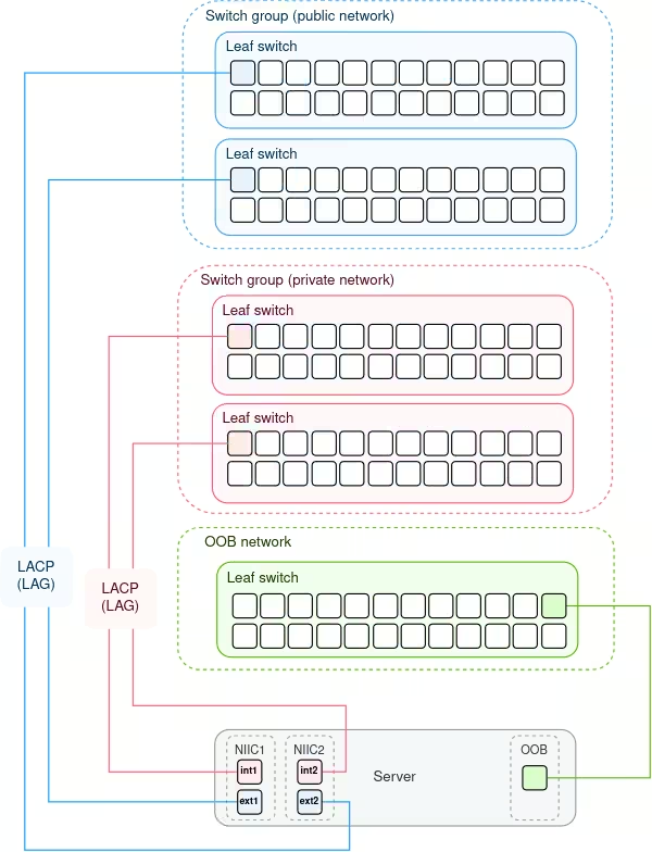
Link aggregation is configured for each pair of public and private ports, in line with our interface naming convention:
| Physical interfaces in the LACP link aggregation group | Link aggregation interface | Network |
| int1, int2 | aggi | private |
| ext1, ext2 | agge | public |
In our environment, public and private interfaces are either assigned directly to physical ports (e.g., int1, ext1) or to logical aggregation interfaces (e.g., aggi, agge) when link aggregation is in place.
Servers without link aggregation
Servers with a single dual-port network interface controller (NIC) do not support link aggregation. Instead, public and private IPs are assigned directly to physical interfaces (int1 and ext1). Network traffic flows directly through physical interfaces, without logical bundling or failover provided by LACP.
These servers are connected as following:
| NIC | Interface name | Network |
| NIC1 | int1 | private |
| ext1 | public | |
| OOB | OOB |